
-69%

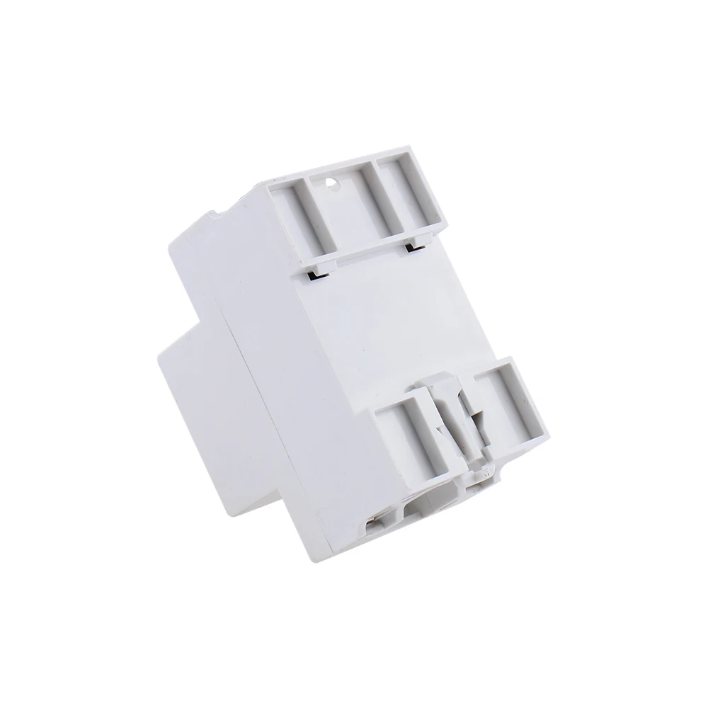
DF-96D DF-96DK Water Level Controller Switch 20A 220V Water Tank Liquid Level Detection Sensor Water Pump Controller 2M Wires
$6.07
Reference price: $19.43
Save 69%
Qty:
- Fast delivery
- 30-day returns
Ships to Canada · Delivery Approximately 7 days (supplier estimate)
Sold by TBII
Specification | |
Type: | DF-96DUpdatedversion |
Workingvoltage: | AC220V/50HZ |
MaxCurrent: | 20A |
Installation: | DinRailMount |
Powerconsumption | ≤2W |
transmissionsignal: | 500M |
Size: | 126*88*51mm |
Package include:
1pcsAutomatic Water Level Controller Switch
3pcs 200CM Sensor
Single-control UP pool (water storage) installation instructions shown in figure 1

A(red)—Upper water level control point. When water level gets to A point,
the probe touch water and controller can stop the pump by auto.
B(blue)—Lower water level control point. When water level gets off B point,
the probe out of reach water and controller can start the pump by auto.
C(black)—Should be placed in bottom of pool as the common line.
D(green) and E(yellow)are connected with C (black).
Single-control DOWN pool(drain water)installation instructions shown in figure 2.

E—Upper water level control point. When water level gets to E point,
the probe touch water and controller can start the pump by auto.
D—Lower water level control point. As liquid level gets off D point,
the probe out of reach water and controller can stop the pump by auto.
C—Should be placed in bottom of pool as the common line.
A&B—disconnected
1 . Lack of water protection installation instructions shown in figure 3.

C&D—Lower water level control points. When water level gets off this point,
C or D probe out of reach water and controller can stop the pump by auto.
E&C—short-connected;
A&B—disconnected
2 . Joint control UP and DOWN pool installation instructions shown in figure 4.

A—Upper water level control point in UP pool. When water level gets to A point,the probe touch water and controller can stop the pump by auto.
B—Lower water level control point in UP pool. When water level gets off A point, the probe out of reach water and controller can start the pump by auto.
C—Should be placed in bottom of UP and DOWN pools as the common line.
D—Lower water level control point in DOWN pool. When water level gets off D point, the probe out of reach and controller can stop the pump by auto.
E—Upper water level control point in DOWN pool. When water level gets to E point, the probe reach water and controller can start the pump by auto. Then pool starts to drain water. If not, E point disconnected
Used to solve problem:
1. On power but no work:
a. Check the red indicator is on or not. If not, make the connection is good enough;
2. When water level is above or below probes but the pump does not start or stop by auto, Please check it like the following.
a. Whether the probe is placed too high or low so that water level can reach or out of reach it;
b. The connection of upper &lower line or probe is dislocation by error or short connected;
c. To check the probe whether it is rust or not or the connection is good enough.
d. C- Check the common line whether it is placed in the lowermost bottom of pool.
English model - DF-96DK model


English model - DF-96DK model


Ruassian model - DF-96DK model

| Category | DIY, Tools & Hardware › Tools & Equipment › Measuring Tools |
|---|---|
| Availability | In stock |
| Ships to | Canada |
| Buyer Guarantees | 15-Day No Update Refund & 60-Day No Delivery Refund |
No reviews yet
Be the first to share what you think of this product.


Fast Delivery
Nationwide shipping
Best Price Guarantee
We'll match any price
Easy 30-Day Returns
No questions asked
Secure Checkout
256-bit SSL encrypted